What's New?
Latest updates March, 2019. Some of these projects are in progress. I'll update them when they are completed.
Useful links
The links below are related to projects in this section.
Below are links to some other related material. Note that if a datasheet is marked preliminary, you should double check pinouts with an additional source.
- 76477 Circuit by unknown author
- SN76477 Datasheet
- SN76477 Article Reprint
- Accurate pinouts of SN76477 and SN76488
- 76488 Preliminary Datasheet
- 76488 Circuit 1 by unknown author
- 76488 Block Diagram from unknown source
- SN94281 Datasheet Page 1
- SN94281 Datasheet Page 2
- SN94281 Datasheet Page 3
- SN94281 Datasheet Page 4
- SN94281 Datasheet Page 5
- SN94281 Datasheet Page 6
- SN94281 Datasheet Page 7
- SN94281 Datasheet Page 8
- SN94281 BeepBox Project unknown author
- Baby 10 Sequencer
- Cascaded 4017 Sequencer
- Engineers Notebook II - 1982
- Popular Electronics Aug 1977
- Popular Electronics Sep 1977
- Popular Electronics Dec 1979
- Popular Electronics May 1980
- Popular Electronics Feb 1981
- Radio Electronics Jan 1984
- CineMagic Magazine #14, 1981
- CineMagic Magazine #18, 1982
- Electronic Music Circuits - The Reprints
Electronic Projects (and some archaic chips)
Most of the projects on this page are in progress. If I have completed the PCB and/or enclosure for one of them, you'll be able to find it on the PCB Creation page.
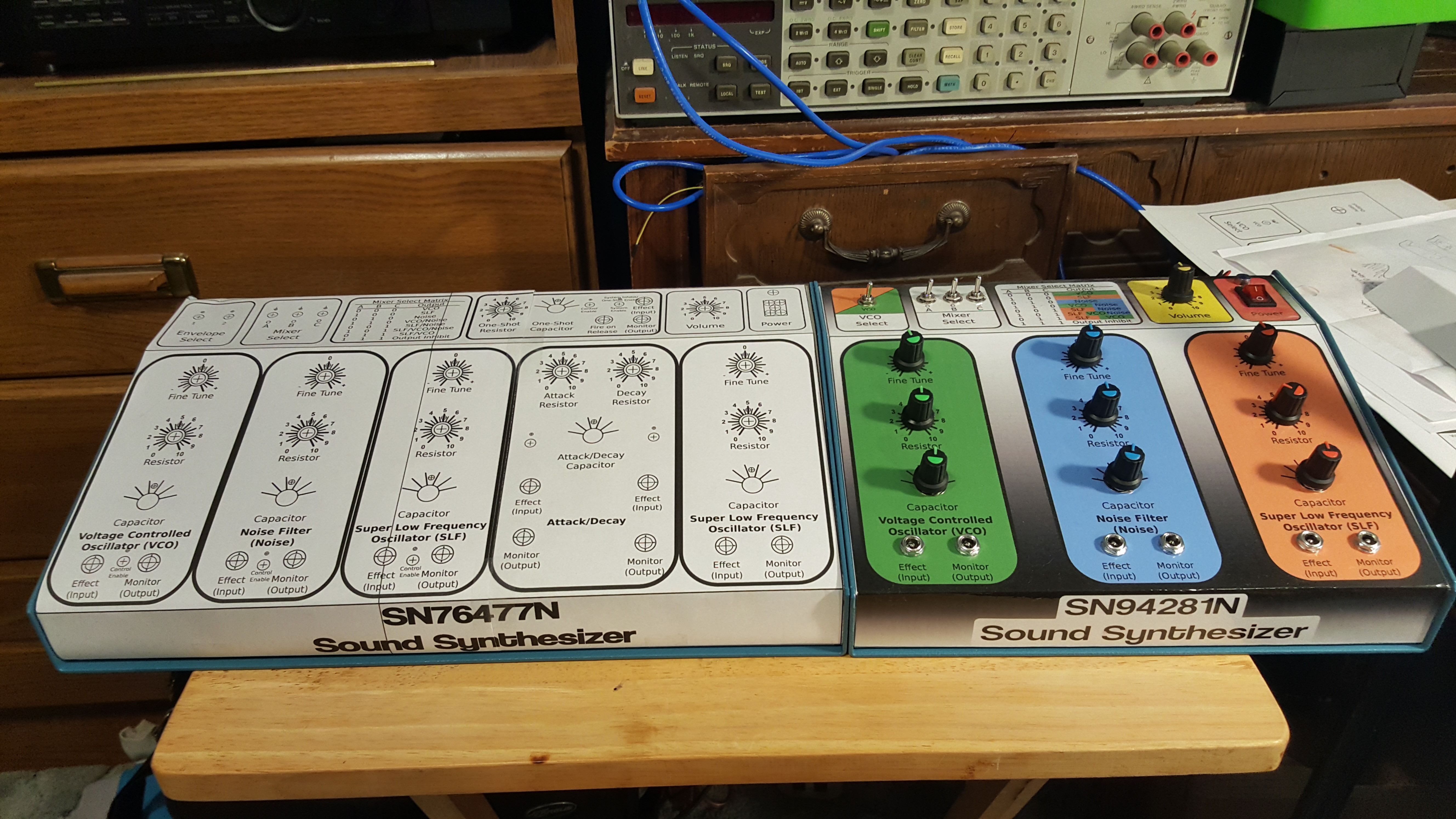
I'm using up some old chips which may not even be available for purchase any more, so I don't expect anyone to actually use any of those schematics or PCB's, but it was fairly difficult to gather as much info as I did about each, so I'll post that here too.
There are schematics for any circuits like these I could find, or links to other pages related directly to any of the chips found on this page. My PCB's are kind of designed on the fly, and I have no real schematics for anything. Some of my circuits are combinations of one or more other schematics I found online and put together. I'll make sure to note all sources.
Also, keep in mind that these are some of the first circuits I've built for 30+ years, and that I'm not the end source of information for any of this stuff. I really do hope that the 12 people left in the world that care about these chips find what they need though.
Texas Instruments SN76477 and SN76477N
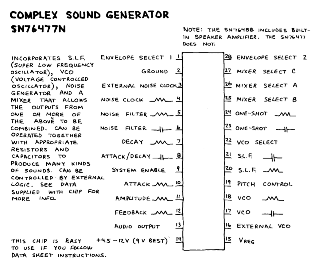
The TI SN76477 or SN76477N Complex Sound Generator chip was one of the first large scale chips that I messed with. I made the demonstration circuit when I was about 16, and when I was about 18 I destroyed it trying to connect it to all of my other sound making devices. None of those devices have survived to this day, with the exception of one or two of the chips. Incidentally, based on schematics from Popular Electronics circa 1979, I recently built a summing amplifier and power supply which would have allowed my to mix all of these things and probably not destroy all of my stuff back in the day. It's nice to know I've learned something in the past 40 years. :-)
I've got original schematics and two of these chips, which are now rare and expensive to buy. Circuits for this chip can be found in the Engineers Notebook 1982 edition, the "SN76477 Article Reprint", and May 1980 Popular Electronics (pg 77), all of which can be found in the links to the left. As time progresses, both of these chips will be used for something, and I currently have everything I need to build the original demo unit x2. There are links in the left-hand column to a few projects using these chips. My final projects will probably be closer to the Saund-Box than SN-Voice.
What does it do?
It makes noise! Wonderfully basic noise. LFO, SLF, Noise generators and Envelope modification make this a really cool old analog chip. I first saw this chip in the Radio Shack Engineers Notebook, 1980 edition. You'll need to build or use an external amp for this one. I'll have links to, and be documenting everything I find related to this chip, because it's a dinosaur and this info might be hard(er) to find soon.. not that anyone has any of these anymore!
Texas Instruments SN76488 and SN76488N
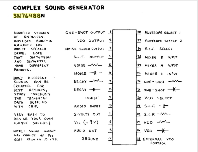
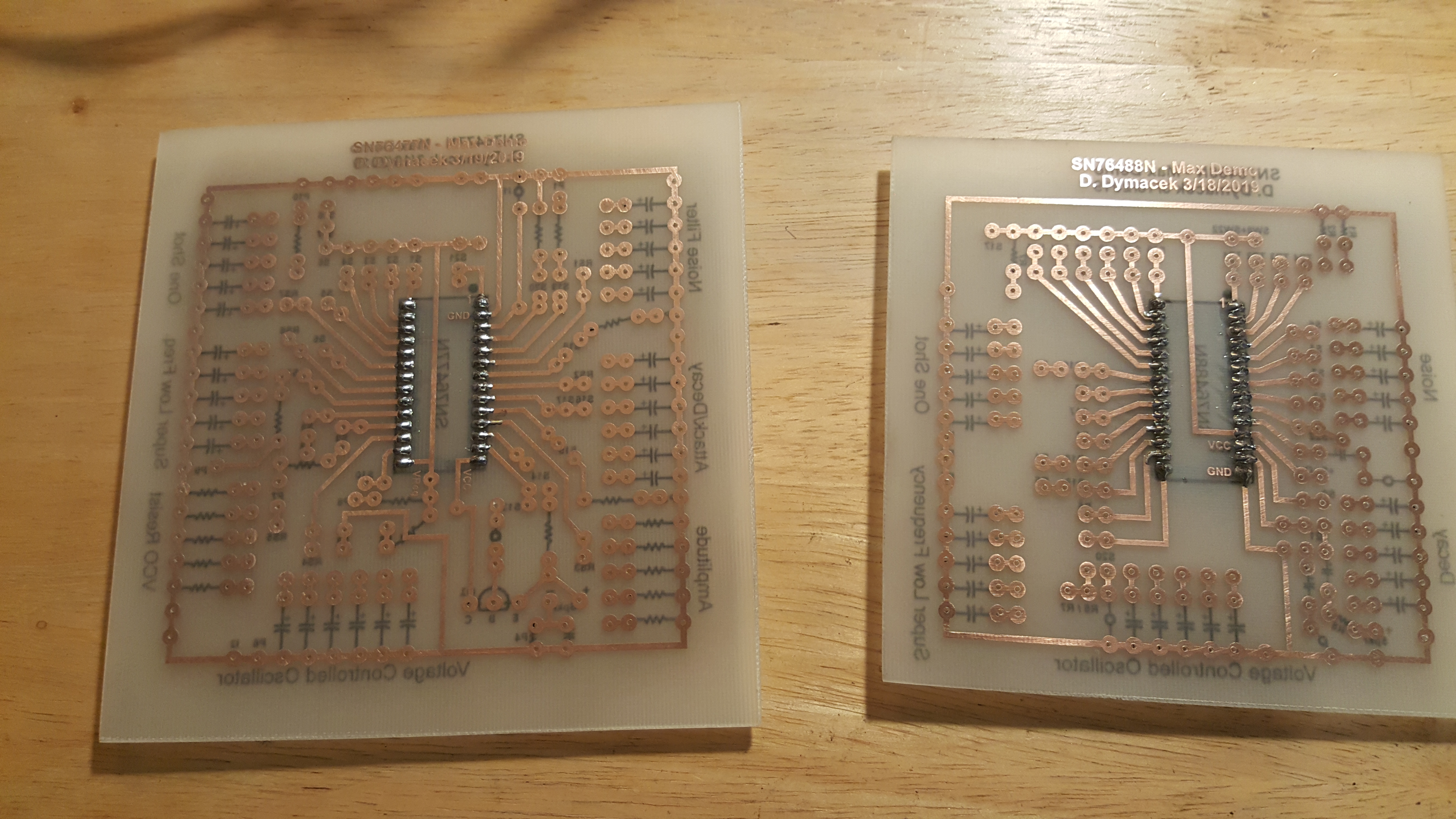
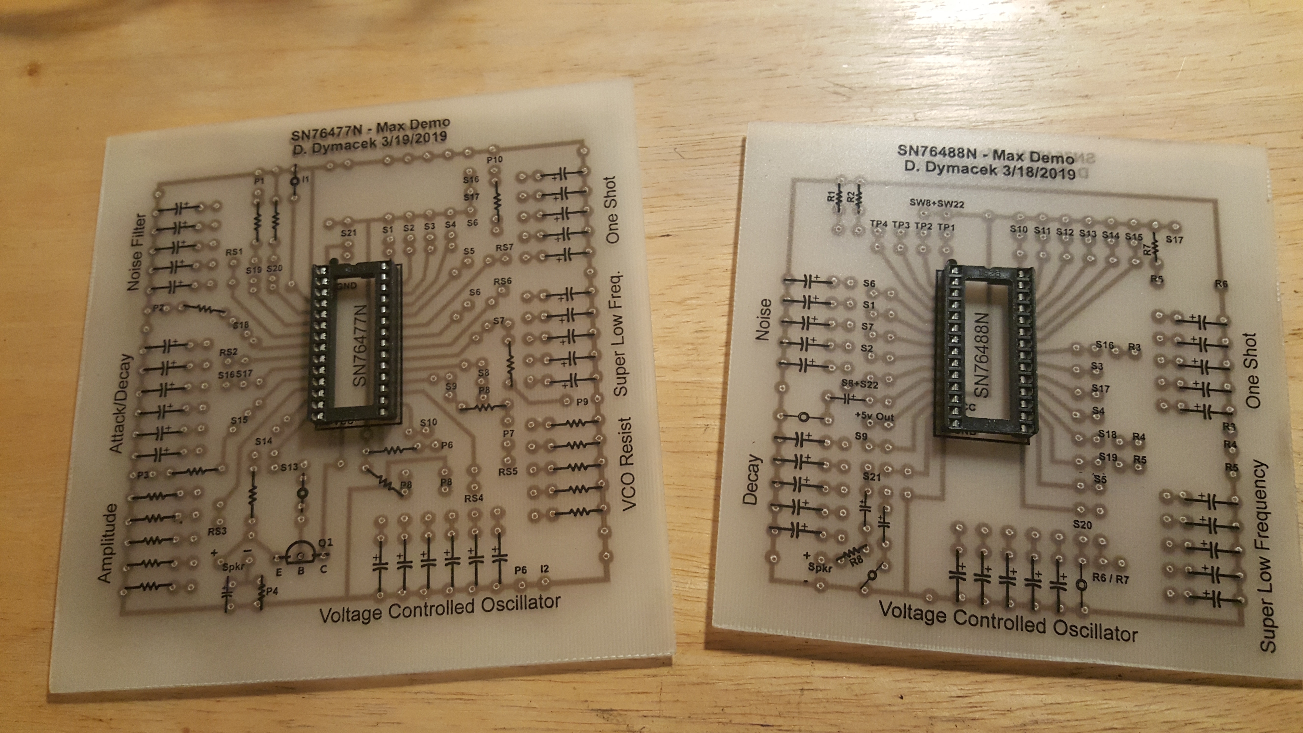
The SN76488 and SN76488N (or NF for a 1.78mm chip) is similar to the SN76477N, but is NOT PIN COMPATIBLE! This is another complex sound generator chip, but this one has an internal amp, so you don't need to mess with amplification circuits. It also has an audio input for mixing other similar devices. Even with these two features, I still don't think the SN76488N is as versatile as the SN76477N, but we'll see. It's still a really cool little noise maker, and is still available on E-bay or whatever. Be careful which CHIP PACKAGE you buy! The NF is a small fat chip with 1.78mm pin spacing, and won't fit into a breadboard. I had to build adapter boards because I bought two of the wrong size. (see the PCB creation page).
Like the SN76477N, I first saw this chip in the Radio Shack Engineers Notebook, 1980 edition. THE SCHEMATIC IS WRONG IN THAT BOOK, and it took me a very long time and a few toasted chips to figure this out. The incorrect schematic was fixed in the Radio Shack Engineers Notebook, 1982 edition (in the links to the left), and that schematic has been tested and works fine. Some of these chips for sale on E-bay are already soldered to an adapter board, so choose wisely when purchasing.
After searching for quite a while, I found several good articles about the SN76488 chip. The PCB shown above is based on the article in Jan 1984 Radio Electronics, pg 69 (in the links to the left). I adjusted the oneshot and VCO circuitry to match the sn76477 demo schematic. There is also a great article in CineMagic Issue #18 from 1982, also in the links to the left. The writer explains how even though the datasheet is bad it still has some good info. He also explains how the build in that article is version two of the build from CineMagic Issue #14, from 1981, again, in the links to the left. I find it interesting that when I bought my first two chips, they were in the clearance bin at Radio Shack, and even though they had staples where the datasheets should have been, there were no datasheets attached. I wonder if they were removed intentionally because people were toasting their chips?
Texas Instruments SN94281 and SN94281N
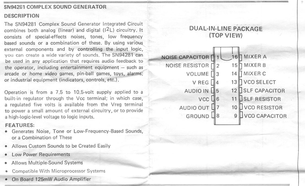
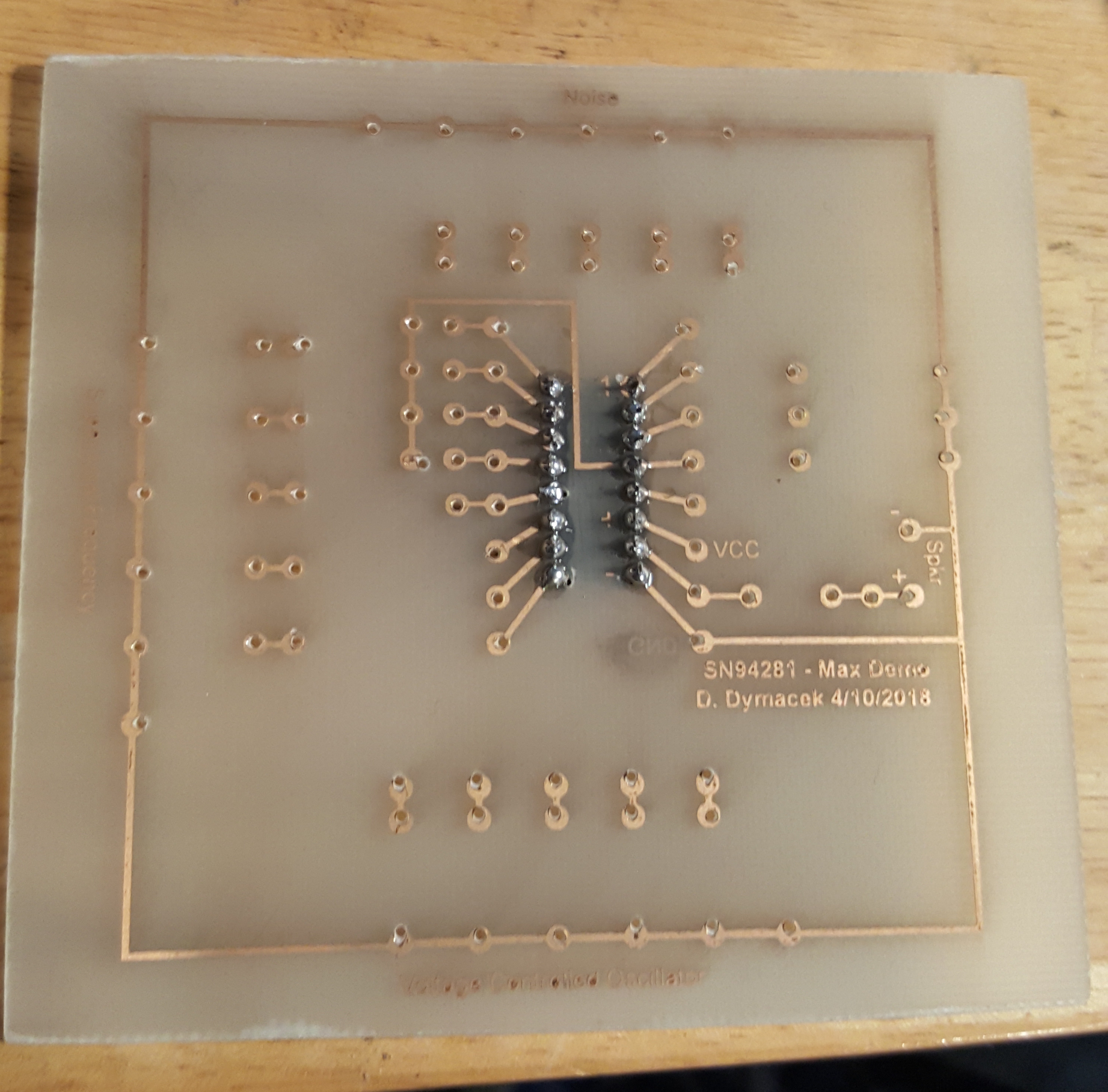
This chip is similar to the SN76477N and SN76488N, but it's in a smaller package size (16 pins), and doesn't do as much as either of the other two. It still makes wonderful noises, but the SN94281 has fewer oscillators and no (direct) envelope modification. Something that seems to have been missed elsewhere is that this chip DOES have voltage controlled volume, which can certainly be used as envelope modification.
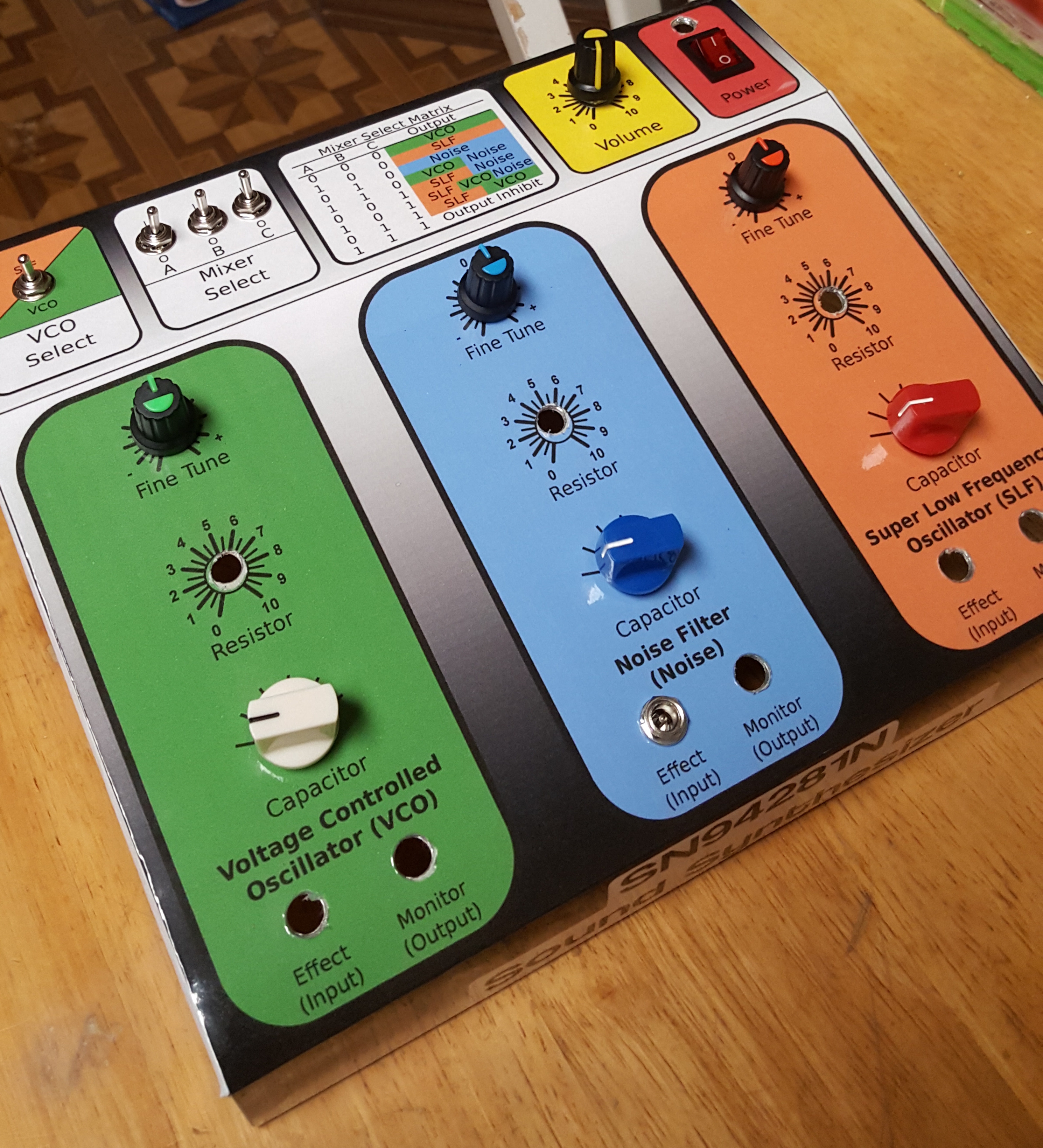
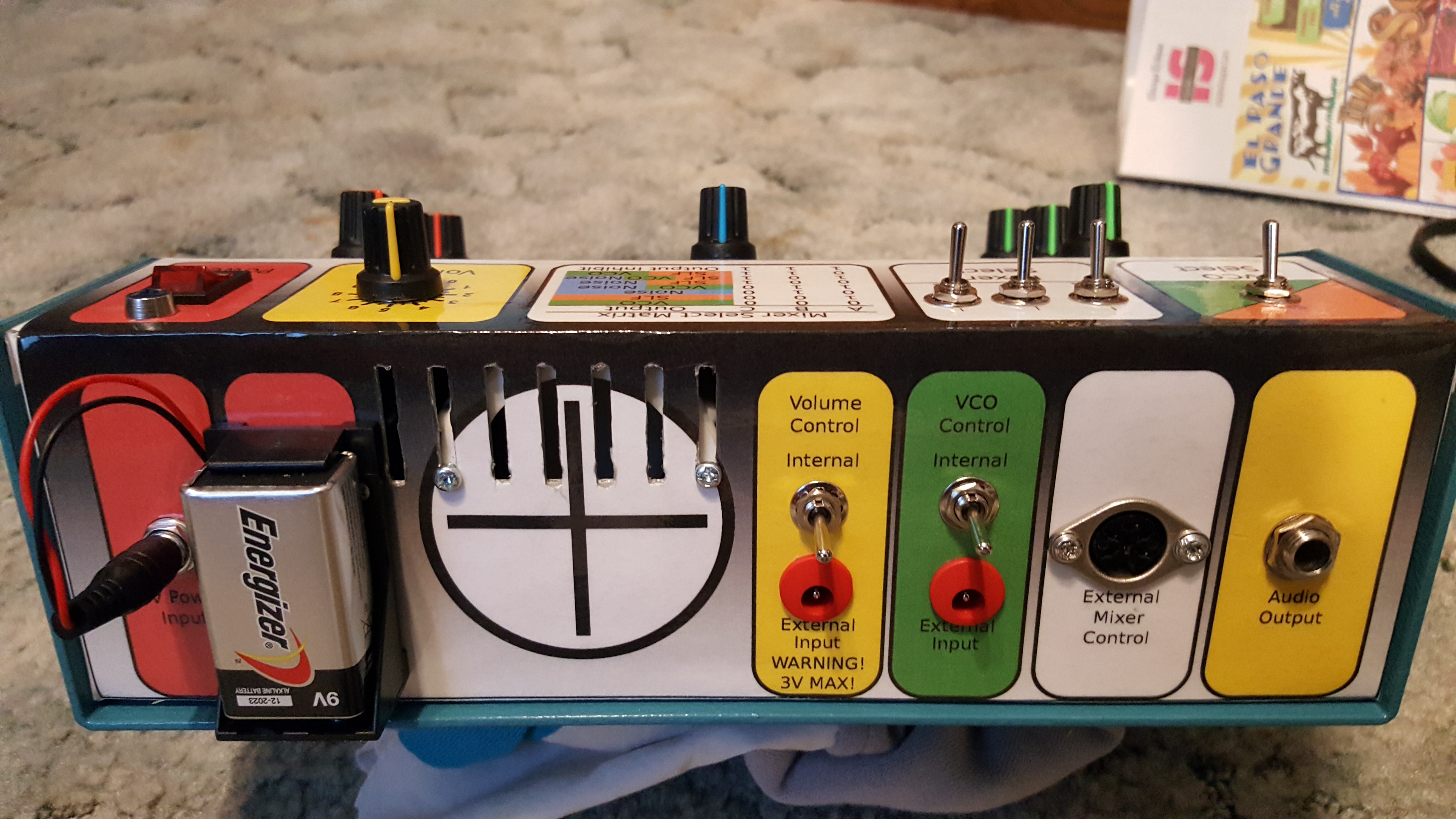
I have finished my basic build and enclosure, and am not disappointed with the results. The VCO can be externally controlled, and so can the "envelope" by means of external volume control, which also works as expected. Check out the videos. I really need more control devices (keyboards, sequencers, etc.) to put this through it's paces. It just might surprise me more than it already has.
These chips are not readily available any more and I only have one chip, so I tried to make the most out of it by designing my circuit carefully, adding connection points in places that might be useful later. SVG files of my pcb layouts and panels can be found here, just in case someone has one of these and doesn't know what to do with it.
Once the sequencer is complete, it will be much more fun to play with this box, at least. Just in experimenting, I've already realized that I would like more sequencers for more control. I gotta say, this stuff is getting pretty Devo.
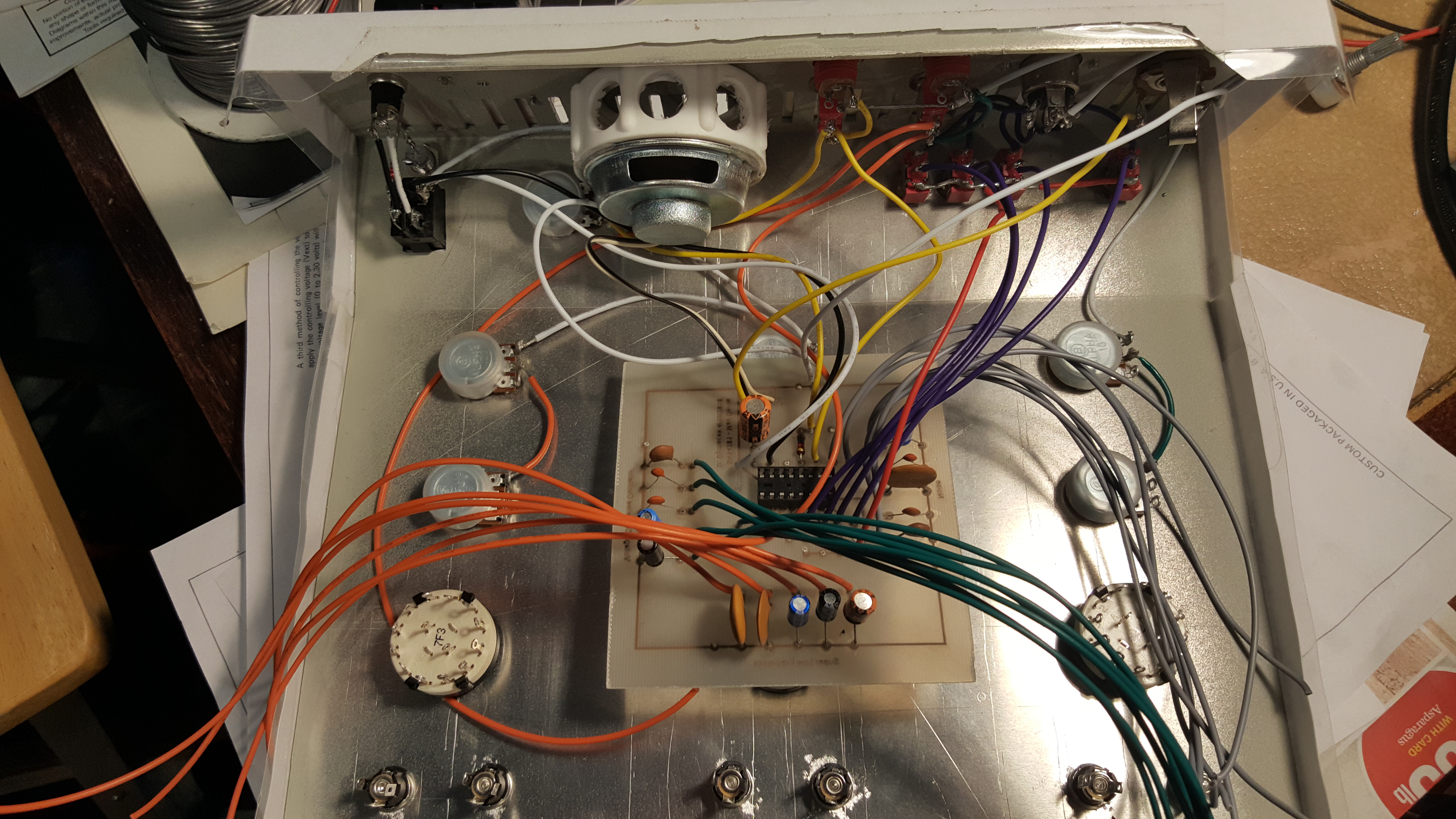
CD4017 2x8 or 1x16 Sequencer
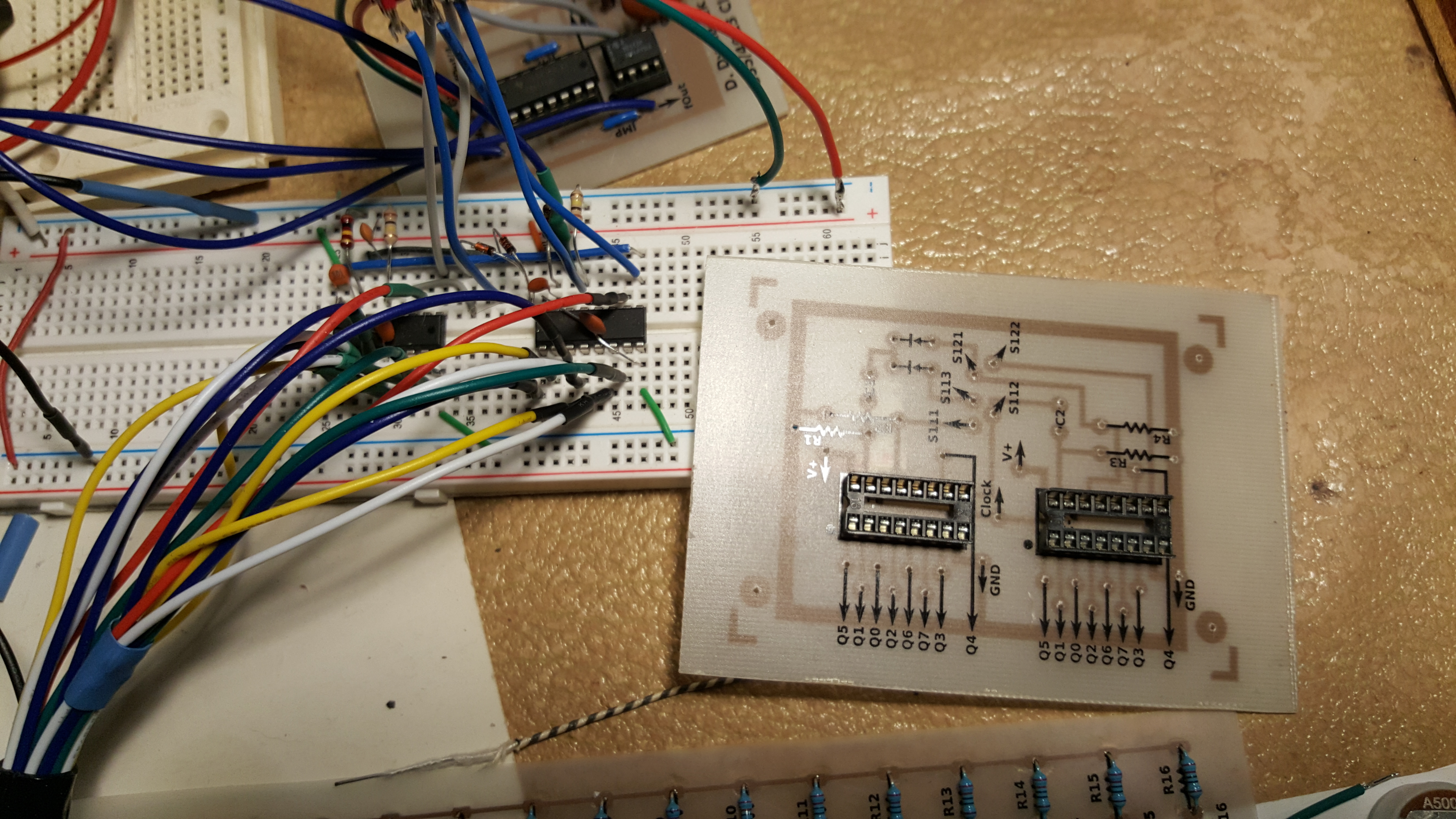
The sequencer I'm building is based on the baby 8, baby 10, or baby 16 sequencers. There are tons of schematics out there, but the one I used is here.
This schematic doesn't account for anything other than cascading two CD4017 chips in order to make a 2x8 or 1x16 sequencer. The LEDs and potentiometer layout is straight from the Baby 10 sequencer schematic. The clock circuit is a simple 555 oscillator followed by a J-K flip-flop for easy frequency division.
Portamento or Glide
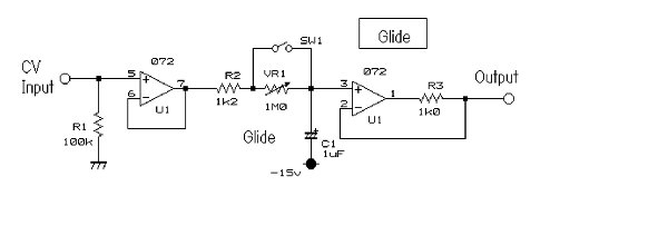
A simple CV step sequencer is nice, but sometimes you just want a bit more. This circuit adds portamento or glide to the CV output of the sequencer. Basically it adjusts the voltages between steps, and you can change how quickly this adjustment happens.

555 and CD4013 Clock Circuit
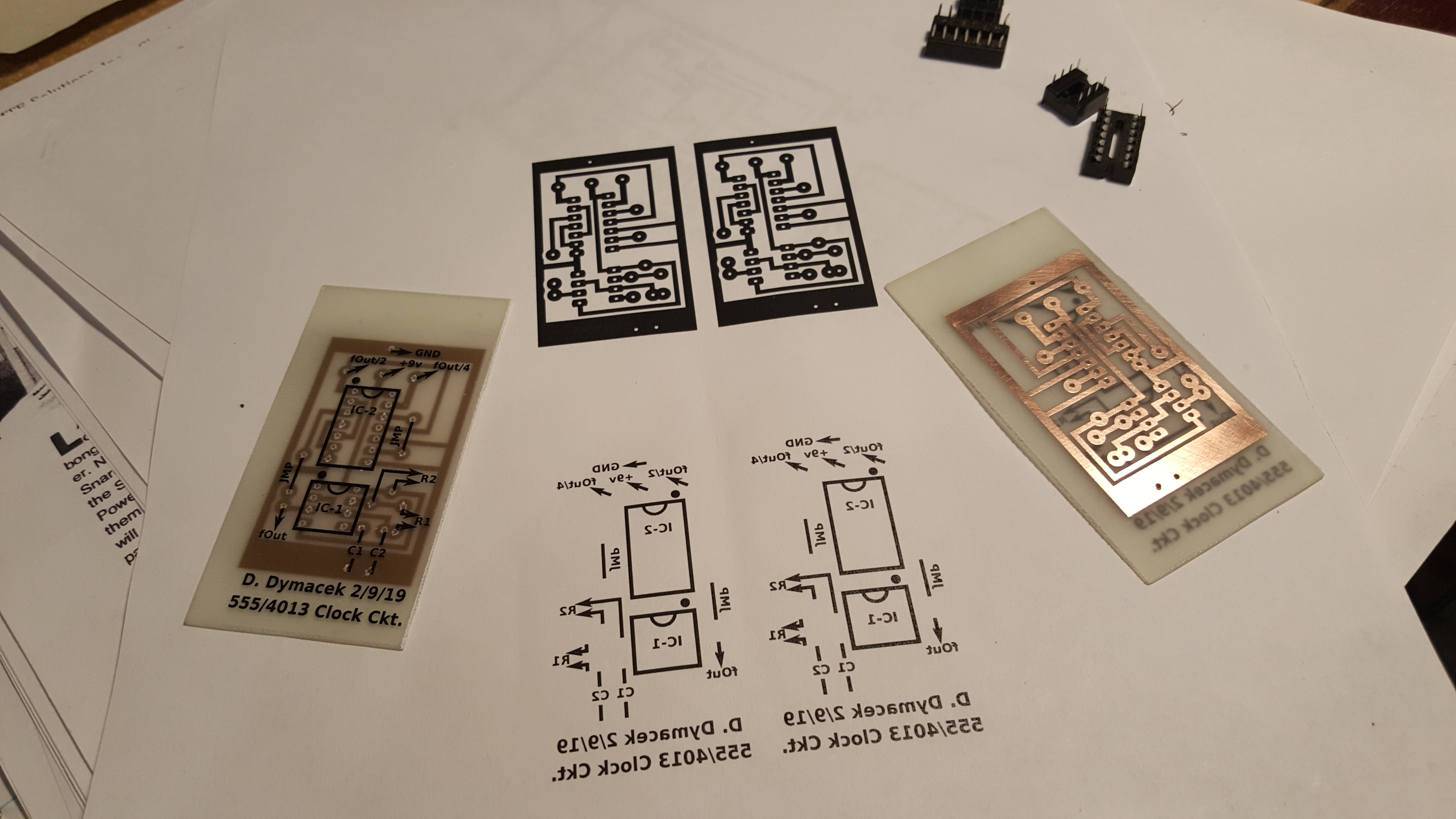
A clock circuit is a pretty important piece of a sequencer (and other synthesizer modules). In the case of the sequencer, it is the "heartbeat", or the thing that actually makes the steps progress.
The clock circuit that I built is about as simple as it gets. Pulse width modulation is possible with a potentiometer, and the frequency range is pretty wide. For something like a sequencer, there are reasonable limits that you want to enforce. Clock pulses slower than 30 seconds would probably be useless when making music (but who knows)?
On the other hand, if you use a very high frequency clock rate, it is actually posible to create a waveshape as the output of your sequencer, which you could use elsewhere in your synth chain.
The Audio Artist
I first built an Audio Artist back in 1980 or so, with some help from my dad. In fact, I think he did most of the grunt work, and I just happily soldered away. It was originally in Popular Electronics (December, 1979 edition), Which can be found in the links to the left. Here's the thing with that early circuit.. there were TWO ERRORS in that article. Popular Electronics has "Letters to the Editor", as well as a section called "Out of Tune" for corrections to articles and circuits, and I found two corrections in there. Without the first correction, which is a missing trace on the PCB, the circuit sounds aweful, but it does make noise. Once you fix that trace, it makes a much nicer noise. I'm pretty sure that dad found that one. BUT when you reverse the transistor it makes a world of difference, and (I'm sure) this is how the thing should have sounded back in 1980.
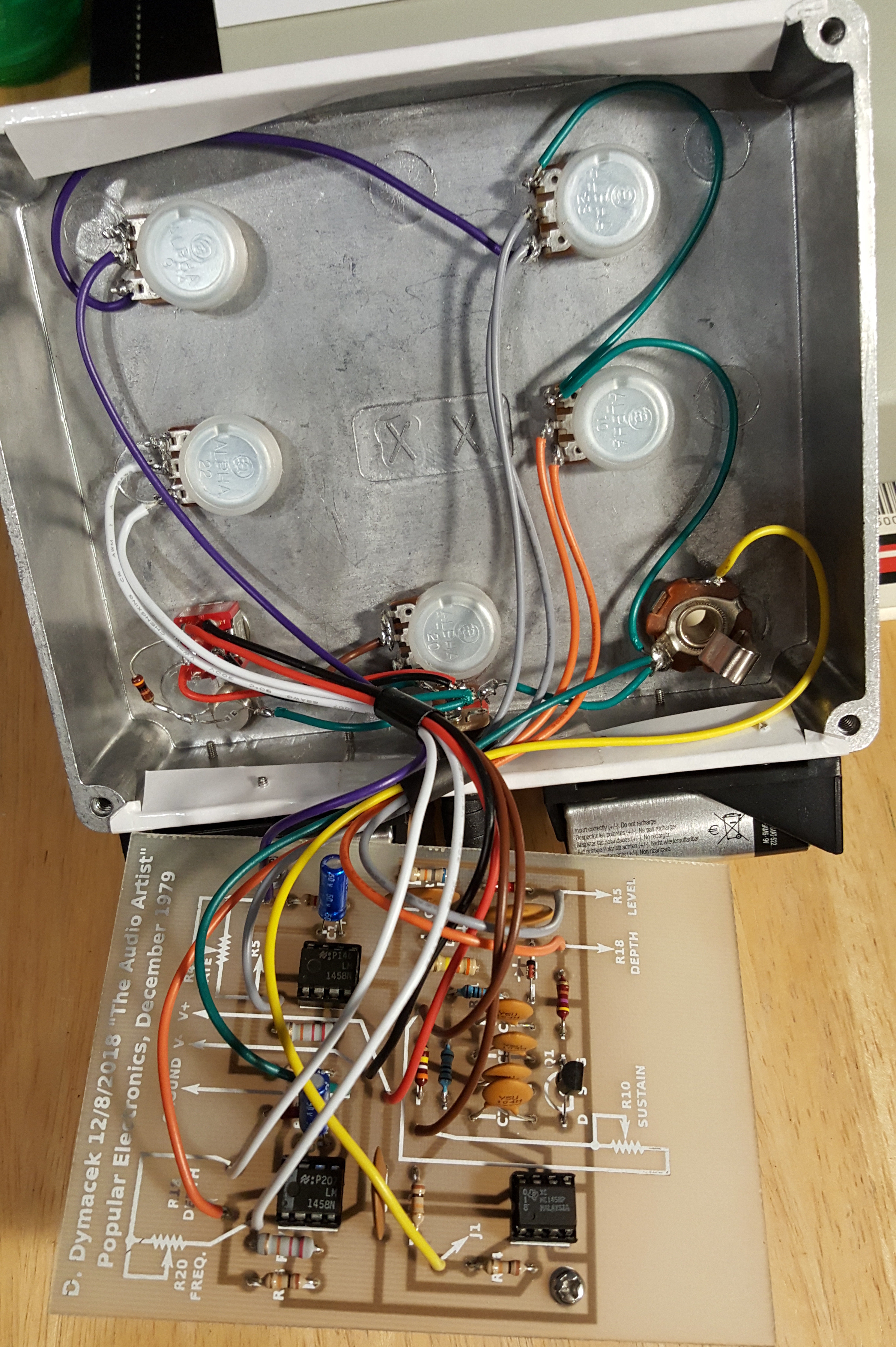
This is a pretty simple circuit to build, but it does lack an amplifier, so you'll need to build one or plug it into some other external amplifier.
Bench Power Supplies
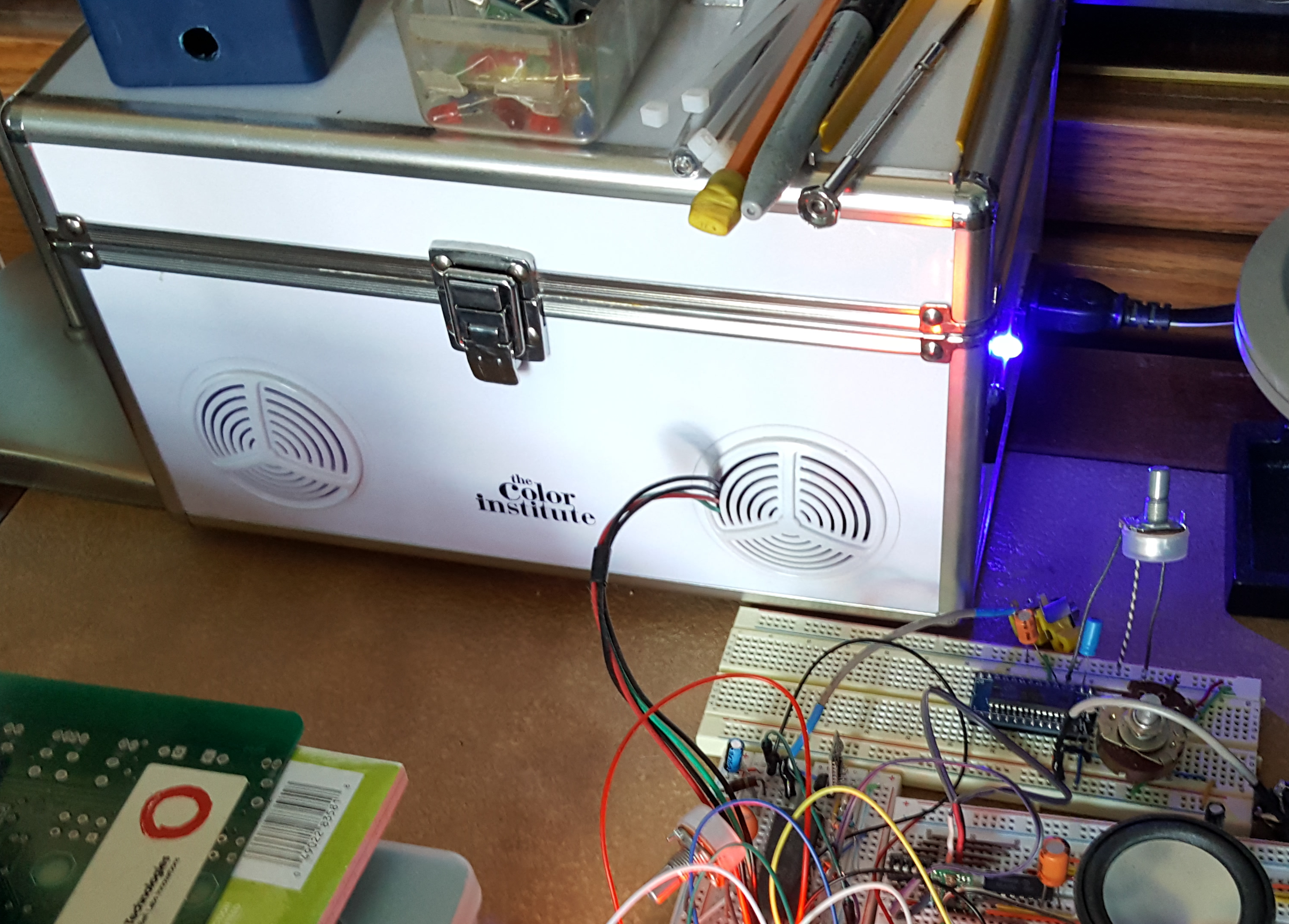
If you're making circuits, they'll probably need power. Common voltages used by IC's are 3v, 5v, and 12v, but if you're trying to make something that will be connecting to a commercial device, you may need something special. For example, some synthesizers operate on 15v, and may need both positive and negative voltages. Where do you get a power supply that can do all of these things? You can purchase a bench power supply, and it might have a variable voltage output (both + and -), but if you need multiple voltages at the same time, you'll probably be spending some money.
What did I do? I used the power supply board from an old VCR! That single board has 5v and 12v outputs, all usable at the same time. I have to admit that the box I put it in is a bit hoaky (shown in the image built into my daughters old cosmetics case), but in the end, that supply didn't cost me a dime, other than time to figure it out and assemble it. I also use a step down buck converter ($3.00) to convert 12v down to 9v. I currently don't have a need for 15v, but there are step up converters for that too. All of my uses are low power (not many amps needed for IC's), so if you need higher power output a dedicated supply is probably the way to go.
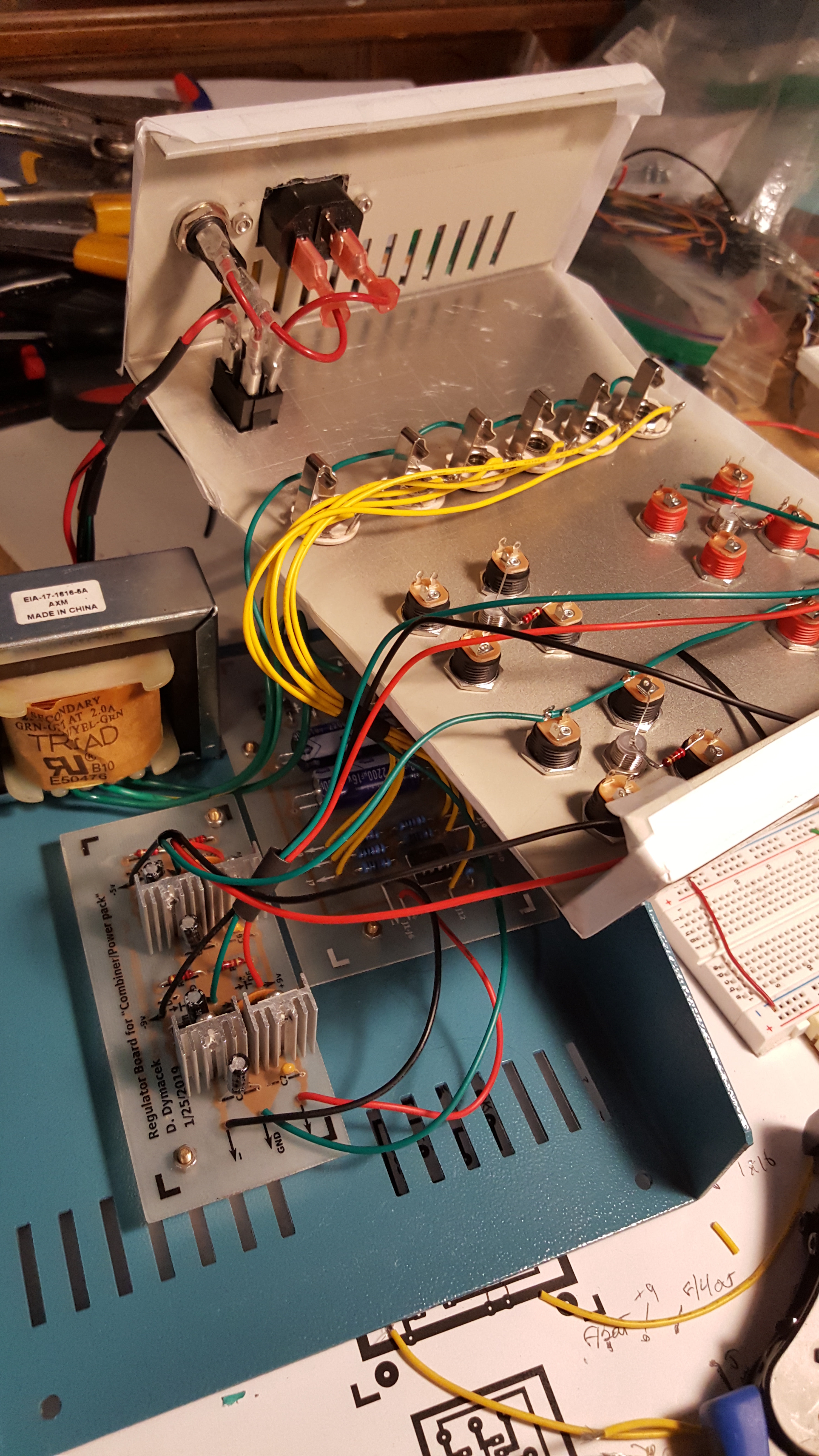
Eventually I needed more than what the VCR power board could provide, so I ended up building a power supply of my own. It is based on an article in Popular Elecronics. The original article was for a non-regulated +/- 9 volt supply, but I added some +/-9 and +/-5 volt linear regulators. The transformer could have handled any regulator up to +/-18v, so if I ever need to use those voltages I could swap out the regulator board, or build another supply.